Introduction to Robotics
Improving the mechanics of our robot
Objectives
- Develop a testing protocol for 3D printed prototypes
- Measure and test robotic behavior under different conditions
Tools and Parts Needed
- Constructed 2-wheel robot with 6 batteries
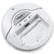
- 3D printed parts
Our Robotic Design
Our robotic configuration of two driving wheels in
front and a skid or wheel in back is a design frequently used in
robots, airplanes, and green cars.
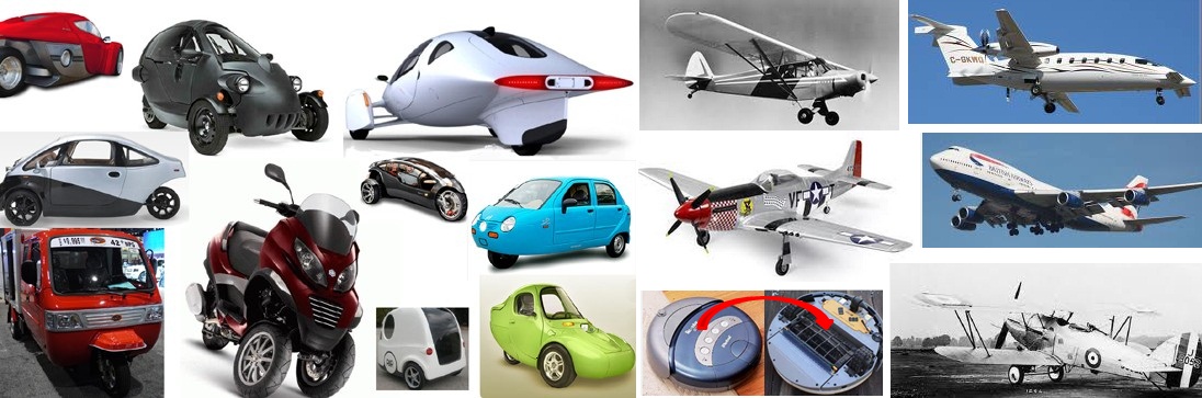
This three-wheel configuration withe the two parallel wheels in
front is frequently called a tail-wheel or tail-dragger, or tadpole, or
reverse-trike. Compared to four wheels, this design has the advantage
of decreased weight, lower rolling resistance, and easier chassis design
for turning (when the outer wheels must travel further than the inner
wheels). This is also the preferred arrangement for builders of
green vehicles and also airplanes.
The other way to configure a three-wheeled vehicle is placing one wheel in front and two in the back. This configuration is sometimes referred to as a tri-car, nose-wheel, or delta configuration. The delta design has actually been around since the beginning of the automobile. In fact, the very first motorcar, built in 1885 by Karl Benz and called the Benz Patent Motorwagon had only one wheel in the front and two in the back. The downside to this design is stability especially if the front wheels turn like a tricycle, so it is usually much less than the three wheel design with the driving wheels in the front.
Although Benz's second design had four wheels and swiftly became the
popular standard for cars, trikes have continued to be standard on
airplanes, green cars, and robots.
Having said this, it is clear that our robot design can be
improved. One obvious area which might be improved is the skid
since it is an obvious source of friction.
Testing Protocol and Requirements
Testing plans, also called testing protocols, are formal documents
that typically outline the requirements as well as the testing
activities to be carried out for a test. You might look back at
lab L3-RoboLab-measurement.html to see the testing protocol we used in that lab. Recall that we used
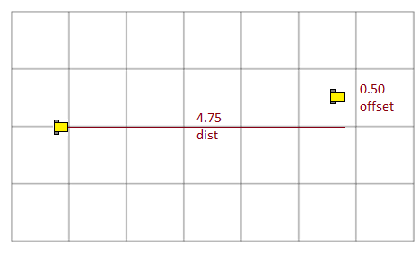
RoboLab to write a program in which the robot drove forward for
1 second forward and backward for 1 second and then drove 2 seconds in the better direction. We ran each test 5 times
and took two measurements (distance traveled and offset from
straight) based upon the floor tiles:
In this lab, we wish to test all of the following:
- friction when starting from a stop
- friction when turning
- friction when driving straight
- friction when driving over smooth tile
- friction when driving across an uneven surface such as a tape to tile or tile to tape transition
Your Lab Report
All lab reports should be self-contained and should contain the primary roles each person played at the top. Such as the following- Lab number: L7
- Time in Roles
- Scribe and Tester
- Robot Handler
- Programmer
- Scribe and Tester
- Testing Protocol: Design a testing protocol which consists of a suite of tests that tests each of the given requirements (I-V):
- friction when starting from a stop
- friction when turning
- friction when driving straight
- friction when driving over smooth tile
- friction when driving across an uneven surface such as a tape to tile or tile to tape transition
- Test Purposes: Be sure
to fully describe each test in your test suite, briefly explaining why
you are choosing this particular test to run, which of the requirements
you are testing, and why you believe this test will serve to help you
understand the part's performance on that requirement. Save what
you tem considers the most interesting of the tests for submission.
- Baseline: Run your first test suite of tests using our usual slider as the baseline test.
- Protocol Tests: For each part to be tested: (Be sure to test at least 3 other 3D printed prototypes in addition to your baseline test.)
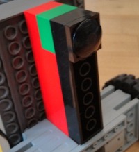
- Attach a 3D prototype part from the set to be tested. You
may use extra Lego parts as needed to make the part operate at an
appropriate height. A photo of the robot with the part attached
would be a nice addition to your lab report--you may use one of these
provided or take your own: https://www.dropbox.com/sh/9xrrzfpuq0b3uf3/hCIOpOgwrM. Please also identify the prototype by letter.
- After attaching the 3D part, clearly identify which the 3D part you are testing, run each test 5 times, documenting the results in your lab report.
- Summary: Complete lab
report by identifying which part you team believes performed the best of those your team
tested. Be sure to fully explain your decision in approximately
3-4 paragraphs.
- Submission: The person who served as the primary Scribe should submit the report yourusername1-yourusername2-yourusername3-L7.docx and the person who served as the primary programmer should submit the last version of the RoboLab test suite program saved as yourusername1-yourusername2-yourusername3-L7.vi. The third team member should submit the names of all of the other team members. Before leaving, you should make certain that all team members have all of the files (email them to one another or pass them around on a flash drive.)