Using NXT Rotational Wheel Shaft Encoders
Objectives
- Learn to use an internal sensor: the rotational wheel shaft encoder
- Synthesis concepts learned in previous labs.
- Practice using containers to do a needed computation.
- Practice event-driven programming.
- Practice working with multiple sensors.
Tools and Parts Needed
- Constructed 2-Wheeled NXT Robot
- Appropriate sensors
In this lab, you will be asked to put together concepts discussed in our previous labs and use the new NXT rotational wheel shaft encoders in order to synthesize and apply these concepts in more challenging programming situations.
If you have not done so, be sure to install the patch from \\Academic\Academic\Mathematics & Computer Science\PearceJ\Resources
In this lab you will be exploring the improved motors, which unlike the motors for the RCX contain rotational wheel shaft encoders.
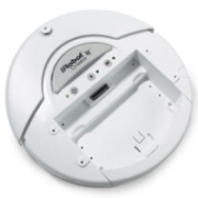
The NXT Motors
 Contained
in
the new Lego Mindstorms NXT kit are three newly designed servo motors. The
new NXT motor delivers high torque because of its internal speed
reduction gear train. Because of that, it also turns slowly and the
efficiency is somewhat reduced. Although this motor could physically
be connected to RCX with a compatibility cable, it is not recommended
for use on a RCX because the high current it consumes is too much for
RCX current output.
Contained
in
the new Lego Mindstorms NXT kit are three newly designed servo motors. The
new NXT motor delivers high torque because of its internal speed
reduction gear train. Because of that, it also turns slowly and the
efficiency is somewhat reduced. Although this motor could physically
be connected to RCX with a compatibility cable, it is not recommended
for use on a RCX because the high current it consumes is too much for
RCX current output.Even more importantly, these new motors include rotational wheel shaft encoders, which tell the NXT the position of the wheel shaft with an amazing 1° accuracy. This is an important new feature because the RCX motors had no built in wheel shaft encoders, so using "time passed" was one common but inaccurate method for applying current, but using "time" in this way is not an accurate way to determine how much a wheel has turned. The NXT rotational wheel shaft encoder wheel and optical fork provide a very accurate rotation sensor function to the NXT motor, which is very useful for such things as determining how much the wheel has turned, and can be used for computing distances traveled or number of degrees rotated.
Using the NXT Rotational Wheel Shaft Encoders
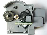 A wheel shaft encoder sensor detects
precisely how many times a motor shaft turns by having an encoder sensor
monitored as the wheel shaft turns. It has 12 slits in the encoder, and
the motor to encoder gear reduction is 10:32, so for each turn of the
wheel hub, the encoders turn 48*10/32=15 turns. Thus, the optical
detectors sees 15*12=180 slits. Using both sides of these slits gives
360 ticks per turn resolution or 1 degree resolution.
A wheel shaft encoder sensor detects
precisely how many times a motor shaft turns by having an encoder sensor
monitored as the wheel shaft turns. It has 12 slits in the encoder, and
the motor to encoder gear reduction is 10:32, so for each turn of the
wheel hub, the encoders turn 48*10/32=15 turns. Thus, the optical
detectors sees 15*12=180 slits. Using both sides of these slits gives
360 ticks per turn resolution or 1 degree resolution.To drive a robot with two motors straight or to turn a precise amount, use the motor sync icon
 and the NXT SMART rotational shaft encoder
  icons.
The motor sync icon tells the "follower motor" to follow whatever "the controller motor" does. The following program will drive straight forward 7.0688 inches, and turn 360 degrees and then stop:

In this example, the motor power icon turns on Motor A (and thus Motor C, because it is following Motor A). The SMART rotational wheel shaft encoder controls Motor A's movement to the specified angular position. Motor C follows along, exactly in sync with Motor B.
Once you have synced two motors, they will only respond correctly to commands for the controller motor. If you want to control the follower motor on its own again, you must turn off the synchronization. To do so, use the motor sync icon without any wires attached to it:
.Driving the NXT Straight
To drive the NXT straight, we should synchronize the wheels and then drive forward. The formula for the circumference of a circle is Diameter x PI. The NXT wheels are 2.25 inches in diameter, so we can find the distance traveled with two wheels synchronized in 1 rotation of the wheel as 2.25 inches x PI = 2.25 x 3.14159... = 7.0688 inches. You may use this number to compute distances traveled as long as you understand that each revolution of the wheel is 360 degrees.
Turning the NXT
To turn the NXT, we can drive just one of the wheels forward. The wheel-base of the NXT is 4 inches, so if only one wheel is turning, the NXT will drive in a circle which is 8 inches in diameter. We must convert this full circle to degrees, so we use the fact that there are 360 in a full circle, which is 2 x PI.
(8 inches x PI) x (360 / (2 x PI)) = 1440 degrees on one wheel for a full 360 degree turn of the robot.
Are these values going to be perfect? No. Because of wheel slippage on the floor, we may not see a perfect response, and the floor surface will make a difference. Even so, this is an improved methodology over the RCXs.
Working with Values in Containers
We have learned that a programmer use the variable to store data or any information by assigning values. As you know, in RoboLab, we store data in container by filling it with the data. In the diagram below, the red container is set to the value of 14. Simple math can be used to store data and change the values that are already stored. As you know, there are other mathematical operations like subtraction, division, and addition. So one can use any math and also any value to use with those operations. In the diagram on the right, the number 12 is being subtracted from the red container. Therefore, if this is run after the above command, the value of the red container is now 2. (14 - 12 = 2)

In this lab, you will need to some kind of arithmetic technique with containers in order to determine how far the robot will turn....
In addition, remember that you can use the Clicks Container,  which allows
the robot to count and store the number of clicks since the Clicks
Container was last reset. By using this, the robot can count the
number of "clicks" made on one touch sensor. One can use this for
example, to count clicks made on one touch sensor while
another another touch sensor is not pressed. Just like any other
container, it is important to zero it before using it. Remember that
we used the following code segment to allow the engineer to enter a
count:
which allows
the robot to count and store the number of clicks since the Clicks
Container was last reset. By using this, the robot can count the
number of "clicks" made on one touch sensor. One can use this for
example, to count clicks made on one touch sensor while
another another touch sensor is not pressed. Just like any other
container, it is important to zero it before using it. Remember that
we used the following code segment to allow the engineer to enter a
count:

One really nice feature of the NXT is that the display of the sensors will happen automatically when they are used.
Team Roles
Decide which of you will fill each of the following roles for this lab:- Engineer: This person will be the only member of the team to handle the IR tower, RCX, Tracker robot, and sensor attachments. The engineer should have THIS web page open on his/her laptop in order to know what to do next.
- Programmer: This person will run the RoboLab program and will create all of the required RoboLab programs. The programmer should have RoboLab open on his/her laptop.
- Scribe: This person will guide the discussion and type the Lab Report as you work on this lab. The scribe should have Word (or another editor program) open on his/her laptop.
Your Task
In this lab, you will create a program which allows the engineer to enter a number between 2 and 8. (You may do this with two touch sensors set up with one as a "counter", and the other as a "stop" to record the number, as we did in an earlier lab.)After this number has been entered and recorded, your robot should drive around and around and around following a polygonal pattern on the floor given by the number entered by the engineer. For, example, if the engineer enters 3 clicks, the robot should drive around and around in a triangular pattern. As another example, if the engineer enters 4 clicks, then the robot should drive around and around in a square. In general, the pattern driven by the robot should be the appropriate one of the following patterns:
 .
.The robot should then continually drive in this pattern on the floor over and over until....
the engineer indicates that the robot should stop. At which time the robot should immediately stop where ever it it and beep. This "stop" indication must be done with a sensor. I suggest that you use one of the two touch sensors. This command to stop must be detected by the robot at any time, which means you will want to use event handling
Background Geometry Needed to Compute the Robot's Turn Angle
When the robot makes each turn in the polygon, how far does it need to turn? Consider, the following images of a selection of the regular polygons:
. . .
 .
. .
.
. .Mathematicians call angles colored in red in the above images "exterior angles" of the polygon. If you imagine the robot driving straight along the side as it goes counter-clockwise around the polygon, you should see that the "exterior" angle is exactly the angle which the that robot needs to turn through in order to be able to drive along the next side.
| So, our next question is how
big is the exterior angle of a regular polygon? Finding the size of the each exterior angle of a polygon is actually pretty simple. It is a theorem from geometry that for all polygons, the sum of all of the exterior angles is always equal to 360º. Note that each polygon has the same number of exterior angles as it has sides. Since all the exterior angles in a regular polygon are equal in measure, to find the measure of each exterior angle that our robot must turn, we just need to divide 360º by the number of exterior angles. Thus, the turn our robot must make is just 360º / n, where n is the number entered by the engineer. Isn't that a surprisingly simple computation?? |
An
observation from a student:
"This makes so much sense! If the robot is going to drive
around a triangle, it has to turn 1/3 of the way around each
time. So, in general, it has to turn 1/n of all of the way
around each time. And, you show us how to make it turn all the
way around..." |
With that Mathematical background, you should be ready to design your algorithm...
You will need to decide what sensors you will need and where they will be connected.
Next, use PseudoCode to design a program which does the following:
- Robot detects the number entered by the engineer, and the indication that it should begin driving...
- Robot computes the amount of time it will need to make the appropriate turns. As you construct your algorithm, be sure that your robot will do something appropriate if the engineer enters less than 2 or more than 8 clicks. If you are working after class on this lab, you might consider programming the robot not to move at all if the engineer enters only 0 or 1 clicks.
- Robot drives around and around and around in the appropriate polygonal pattern. The polygon's sides should each be 2 feet long. Note that the computations for the sides lengths and the turn angle should be computed as best as you can compute it... the instructor understands that the side lengths and the turning will not be perfect due to wheel slippage... just do your best to get the robot to drive in a regular polygonal pattern by using a correct computation. Note that the corners of your polygons should be pointed, not curvy--this is most easily accomplished by stopping one wheel while the other wheel drives forward. Note alll this precision requires the new NXT icons be used.
- When the robot detects the engineer's "stop" indication, at which time the robot will immediately stop where ever it is and beep. Note that your robot should drive forever if the engineer never enters the indication to "stop." Hint: This should be accomplished as an event because it can happen at anytime, but do not add this event in to the code until you get everything else working!!!
- Be sure to include explanatory comments to your RoboLab code by
using the Edit Text icon:
 In particular, it is required that you add
the following comments:
In particular, it is required that you add
the following comments:
- Lab L15
- All of your team member's names
- Appropriate comments on the computation of the turn.
- Comments about what the robot will do if the user enters 0 clicks, 1 click, and more than 8 clicks.
- Finally, modify your pseudocode, robot, and RoboLab program to improve your robot's performance.
- Answer the questions in your Lab Report.
Your Lab Report
All lab reports should be self-contained and should contain all of the following information at the top:- The lab number: Lab L15
- How long each person served in each of the roles:
- Driver:
- Navigator
- Your Pseudocode: Include the final version of your pseudocode in your Lab Report.
- Your Robot: Briefly describe which sensors and actuators need to be attached to which ports for your implementation.
- Computation: Explain your computation and how you arrived at this algorithm.
- Error Handling: Discuss what your robot will do if the engineer enters too few or too many clicks.
- Your Success: In a paragraph or so, describe how to use your program and whether or not your robot functions as desired. If not, what goes wrong and under what conditions?
- NXT vs RCX: Describe how this lab would have been easier or harder on the RCX and why.
- Comments and Suggestions: Write a paragraph that summarizes your team's reaction to RoboLab and to this lab. If there are any problems you encountered or any questions that remain, please ask! Also, be sure to include any suggestions you have for how this lab could be improved.